This is the first post in a series where I open up the working knowledge behind the multi-axis force and torque sensors we design and calibrate. Not the textbook version. The version that comes from building five sensor generations, calibrating them on a bench, and being wrong often enough to write the lessons down.
We start with the idea everything else depends on. A force sensor does not measure force. It measures something that is related to force, and the relationship is only known after calibration.
The number on the wire is not a force
Follow the signal from the load to the computer. A load bends a metal flexure. Strain gauges glued to the flexure change resistance by a few parts per thousand. A Wheatstone bridge turns that into a few millivolts. An analog front-end amplifies it, a 24-bit ADC turns it into counts, and firmware multiplies the counts by some scale factor before streaming them out.
Every one of those steps carries its own gain, offset and imperfection. So what arrives over USB or Ethernet is a firmware-scaled pseudo-load. It has the shape of a force reading. It may even have the units label of one. But it is not yet an engineering value you can put in a report.
Why one axis leaks into the others
On a single-axis load cell the story ends with a scale and an offset. On a multi-axis sensor it does not, because axes are never truly independent.
Push straight down on a six-axis sensor and the Fz channel responds, as it should. But Mx and My move too, a little. Twist it about Z and you will see a whisper on Fx. This is crosstalk, and it comes from physics, not from bad workmanship:
- The flexure geometry couples deformations. A shear beam that bends under Fz also twists slightly under Mx.
- Gauges are never placed at exactly the ideal spot, with exactly the ideal orientation.
- Machining tolerances, adhesive thickness and bridge resistor mismatch all add a percent here and there.
- The load is rarely applied exactly where the design assumed. A lateral force at 5 mm above the reference surface is also a small moment.
A good mechanical design keeps crosstalk to a few percent of full scale. It never reaches zero. So instead of pretending each channel is its own sensor, we treat the whole device as one linear map: a vector of loads in, a vector of channel readings out. Calibration is the job of inverting that map.
What a decoupling matrix actually is
Write the loads you want as a wrench vector W. For a six-axis sensor that is [Fx, Fy, Fz, Mx, My, Mz]. Write what the sensor streams as a raw vector raw. The calibration says:
Each term earns its place:
- zero is what the channels read with nothing on the sensor. It is captured on the bench, unloaded, as the mean of a few hundred samples. It ships inside the calibration report because every later measurement subtracts it.
- M is the decoupling matrix, sized axes by channels. Its diagonal holds the sensitivities, the "how many newtons per count" numbers. Its off-diagonal entries are the crosstalk corrections, the small negative and positive terms that cancel what Fz leaks into Mx.
- bias absorbs anything the zero did not, such as the weight of a fixture that was on the sensor during calibration but is not part of the measured load.
Nobody writes M down by hand. You apply known loads, record what the channels do, and solve for M by least squares. Two families of method exist, and the next post is about them: hanging dead weights on levers one axis at a time, or reorienting the sensor under gravity with an IMU watching. Both end at the same matrix.
Calibration is a contract, not a file
Here is the mindset shift that took us longest. A calibration is not a matrix you paste into firmware and forget. It is a contract that every downstream measurement reads.
Our calibration report carries the zero offsets, the per-axis fits, the matrix, the bias, the condition number, the gravity constant used, and the moment reference offset. When the testing software loads that report, it shows a provenance card first: date, condition number, and the constants it will honour. Only then does it turn the raw readout into engineering units and start scoring accuracy and crosstalk.
If the report and the test disagree about which surface moments are referenced to, or which gravity constant was used, the crosstalk numbers will look terrible and the sensor will be blamed. The sensor was fine. The contract was broken.
Why calibration software rots
Calibration software is usually a pile of one-off scripts that nobody trusts twice. We had exactly that: three GUIs and ten scripts grown around three projects. Each worked when written. None could be run six months later with confidence.
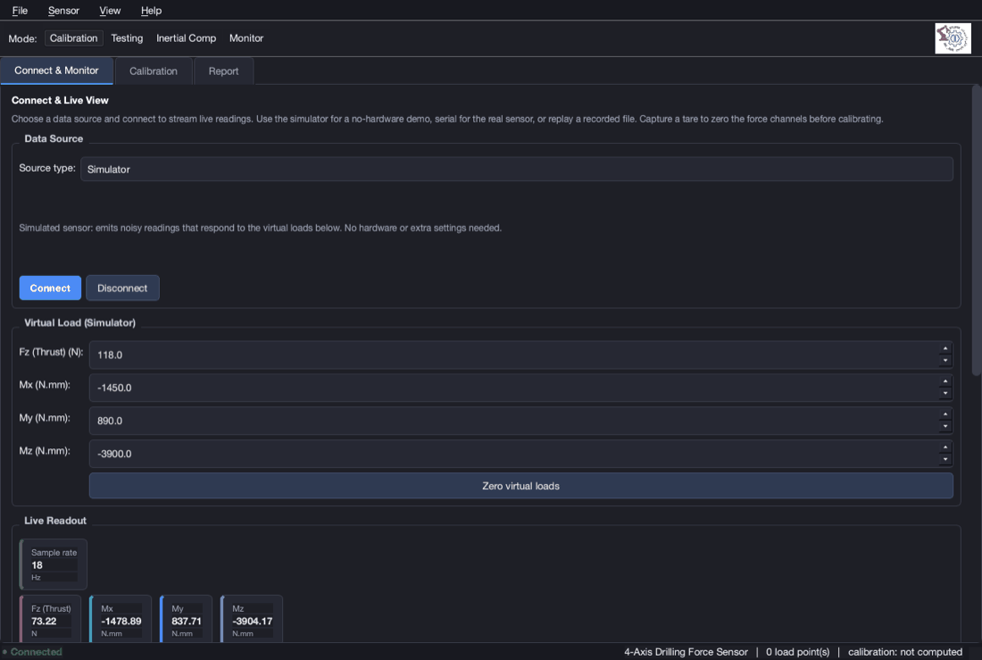
The fix was not a rewrite for its own sake. It was regression-locking. The gold-standard test in our suite takes the real bench captures from a deployed sensor and must reproduce the decoupling matrix that is actually running in its firmware, condition number and all. If a code change moves that matrix, the change is wrong until proven otherwise. Over 250 automated checks now gate every change, and the calibration workflow runs end to end on a simulator so it can be rehearsed with no hardware.
That is what "only as good as its calibration" means in practice. The sensor hardware sets the ceiling. The calibration, and the software that produces and honours it, decides how close to the ceiling you actually get.
What comes next
Part 2 looks at the five sensor profiles we run today and the two calibration philosophies behind them: why sensors with an IMU are calibrated by reorienting gravity, and why the 6-axis sensor is still calibrated with dead weights on levers.